
23 October 2026, 14:38
Loading...
Overview: Established and promising energy storage technologies in Czechia
Vladimír Wagner
11 September 2018, 16:56
The biggest obstacle to the use of intermittent renewable sources is limited energy storage capacity. There are a number of physical ways to store energy, but the large-scale use of most of them remains considerably limited. Let us look at the options in this area, both globally and in Czechia.
Pumped-storage hydropower plants remain the most widely used option. They have very high efficiency, which can reach around 80 %. Their output can vary widely, reaching hundreds of megawatts. Depending on the size of the upper reservoir, they can provide their rated output for many hours or even several days. They can respond within tens of seconds, enabling effective fast balancing. A detailed overview of their current status and future in Czechia and globally is provided in a recent article on hydropower plants. In the next article in this energy series, focused mainly on Czechia, we will look at other options.
Rechargeable batteries
Another option is the use of electric batteries (accumulators). As early as 1859, French physicist G. R. Planté invented the lead-acid battery. It consisted of pairs of lead plates immersed in a container of sulphuric acid solution. They achieve efficiency of 80 %. Technological civilisation has had extensive experience with their use for a very long time.
Nickel-cadmium (NiCd) and nickel-iron (NiFe) batteries were invented by Swedish inventor Waldemar Jungner, while the latter were introduced into widespread use by T. A. Edison. NiFe batteries alternate iron and nickel plates immersed in an electrolyte based on potassium hydroxide. Their major advantage is that they contain neither lead nor cadmium, which are hazardous to the environment.
Traditional NiCd cells do not require complex control electronics, have a long service life and are reliable. Their energy density is 40 – 60 kWh/m3. They were used in the first systems for large-scale industrial energy storage. These include, for example, GVEA’s BESS system completed in 2003, which can provide 27 MW for 15 minutes. Another installation is a system on the island of Bonaire in the Netherlands Antilles, with an output of 3 MW and capable of supplying power for 2 minutes. It helps regulate local wind and solar sources. It can bridge periods of their rapid outage until backup sources come online. The battery system began operating in 2010 and has supported the island’s path towards sustainable energy.
At present, partly for environmental reasons, NiCd batteries are being replaced by nickel-metal hydride (NiMH) systems with an energy density of 120 kWh/m3 and lithium-ion (Li-Ion) systems. The latter have three times the energy density. Lithium batteries comprise an entire range of types using different chemical reactions, all characterised by the movement of lithium ions between electrodes during charging and discharging. Lithium batteries do not contain metallic lithium; lithium ions are incorporated into structures made of other materials. Lithium metal oxides or phosphates are used for the cathode, and graphite or a compound of lithium oxide and titanium dioxide for the anode. The electrolyte may be a lithium salt in an organic solvent. Lithium cells are assembled into multi-cell batteries, which can then provide the required voltage. An electronic system that monitors operation and determines safety parameters is very important in this case. It must protect the battery from complete discharge.
The first commercial Li-Ion batteries were produced by Sony and Asahi Kasei. Their enormous advantage is their flexibility. They are manufactured in sizes ranging from small units powering mobile phones and other consumer electronics, through batteries for electric vehicles or small rooftop photovoltaic installations, to battery storage facilities for the large-scale power sector. The latter operate in the multi-megawatt range and can provide such output for many hours. Their efficiency exceeds 90 %. They can undergo thousands of deep discharge and charge cycles. However, their limited lifetime remains a weakness, as does the risk of damage and fire. Technologies ensuring their safe operation are steadily improving. Their energy density is around 300 kWh/m3. Laboratories are, however, working to find new electrolyte types and improvements that would make it possible to reach values of up to 500 kWh/m3. This is particularly important for electric vehicle batteries. One option, for example, is a fluorine-based electrolyte, which would also be non-flammable. This is another important advantage for transport applications.
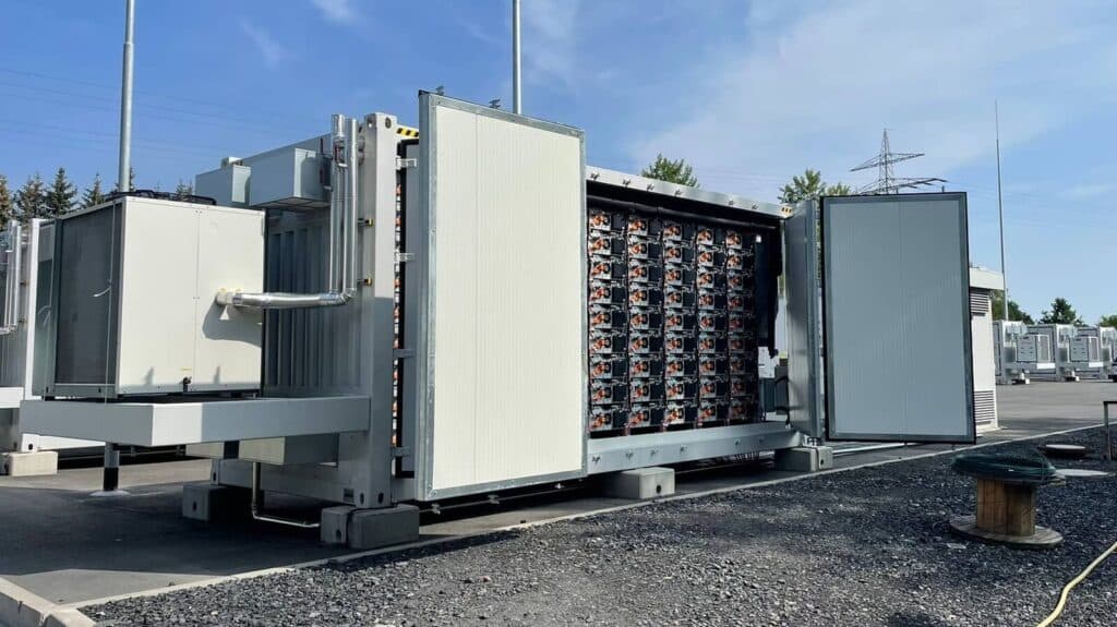
Large numbers of lithium batteries are produced for electric vehicles. In recent years, they have also increasingly been used in battery storage facilities that help regulate the grid. This is enabled by their very rapid response. The largest Li-ion battery array so far was installed in Australia and connected to the grid at a wind farm operated by French company Neoen. It was supplied at the end of 2017 by Elon Musk’s company and completed in less than 100 days. Its output is 100 MW and its capacity is 129 MWh. The battery storage facility helps balance grid fluctuations in South Australia. This large-capacity facility remains an exception, but installations with output of around 10 MW and capacity of around 10 MWh are quite common. They successfully help regulate grids that must cope with an ever-growing share of variable renewable sources. Further large storage facilities are also being prepared. At the same site as Musk’s project, British billionaire Sanjeev Gupta also intends to build a large-capacity storage facility with output of 120 MW and capacity of 140 MWh. A storage facility with maximum output of 150 MW is planned in South Korea, while a 200 MW battery is planned in California.
In Czechia, the largest installation so far is Siemens’ SIESTORAGE facility installed by E.ON in Mydlovary. Its output is up to 1,6 MW, although its grid connection agreement limits it to 0,99 MW, and its capacity is 1,75 MWh, which can be expanded to 10 MWh. A second facility was built by Solar Global in the village of Prakšice. It has output of 1 MW and capacity of 1,2 MWh. Other large-capacity storage projects are being prepared in Czechia. ČEZ also wants to build a large storage facility.
Sodium-sulphur (NaS) batteries must operate at temperatures between 300˚C and 350 ˚C, required to melt the sodium and sulphur. They have an energy density of 150 – 240 kWh/m3, three times higher than lead-acid batteries. They were originally developed by carmaker Ford in the 1960s. The active materials in this case are liquid sulphur as the positive electrode and liquid sodium as the negative electrode. The electrodes are separated by solid sodium-aluminium ceramic, which also acts as the electrolyte. This ceramic is permeable only to positively charged sodium ions. The efficiency of these batteries is very high, typically 89 %. They are used for large-scale industrial energy storage mainly in Japan, where their total installed output is roughly 300 MW and they can supply power for several hours.
Flow batteries
These are sometimes referred to as flow or liquid batteries. They are a type of battery in which charging and discharging are enabled by reactions between two chemical substances dissolved in the system’s liquid, in two tanks usually separated by a membrane. One contains a positive electrolyte and the other a negative electrolyte. The technology is similar to both fuel cells and batteries. One of the major advantages is the continuous possibility of replacing, regenerating and reusing the electrolyte liquid. Another is their very long service life, in the order of 10 000 discharges. The membrane is the critical weak point for lifetime, but it can be replaced relatively easily. A disadvantage is their lower energy density, ranging from 15 to 25 kWh/m3. There are several types of these batteries, including redox, hybrid and membraneless systems.
The term redox refers to the reduction and oxidation reactions that underpin the charging and discharging process of redox flow batteries. True redox batteries are those in which all chemical components active in the charging and discharging process are in dissolved form. Examples include vanadium redox flow batteries and iron-chromium systems. Vanadium flow batteries were first used in Australia in 1986.
Hybrid systems have one of their components in solid form; these include systems using zinc and bromine, or zinc and chlorine.
These batteries would have a major advantage in electric vehicles. Instead of recharging, the electrolyte could be exchanged at a filling station, making the process very similar in time terms to refuelling petrol and diesel cars today. The collected electrolyte would be transported to dedicated facilities for recharging, which would draw electricity and charge it during periods of surplus.
For large-scale energy storage, their advantage is that both output and capacity can be increased simply by enlarging the volume of the electrolyte containers. Systems for different applications therefore range from output of tens of kilowatts to tens of megawatts, and capacity from 500 kWh to hundreds of megawatt-hours.
The largest flow-battery-based storage facility is being built near the Chinese city of Dalian, where there are many wind farms and insufficient transmission capacity. It will be a vanadium redox system with total output of 200 MW and capacity of 800 MWh.
Superconducting magnetic energy storage
Very interesting storage systems make use of superconductivity. This is a state in which electrical resistance in materials virtually disappears completely. In addition to conventional superconductivity, which occurs at liquid-helium temperatures, high-temperature superconductivity now also exists. Some special materials can thus become superconducting at liquid-nitrogen temperatures. However, high-temperature superconductivity remains more at the research stage than at the stage of practical applications. In this case, electric current is stored in a superconducting coil immersed in liquid helium. It can remain there for a very long time. Systems of this type are denoted by the acronym SMES (Superconducting Magnetic Energy Storage).
The enormous advantages of this storage method are its very rapid response, very high efficiency and very low losses over time. Charging and discharging times are extremely short, while efficiency exceeds 95 %. Total losses could potentially be reduced to below 1 %. Several small commercial units with capacity in the range of several MWh currently exist. Owing to their very fast response, they are primarily intended to maintain high quality of supplied electricity where needed. Test installations have reached capacities of up to 20 MWh.
Mechanical energy storage
One option in this area is rotating flywheels. The simplest version involves mounting the heaviest possible flywheel on the shaft of an electric motor powered by the electricity whose energy is to be stored. When energy is drawn, the electric motor acts as an alternator and the stored energy can be extracted. Steel and conventional bearings were traditionally used for flywheels. However, this limits rotational speed to several thousand revolutions per minute. Capacity rises with the square of the rotational frequency. Modern flywheels are made of carbon composite, rotate in a vacuum and use magnetic bearings. This allows them to reach up to 100 000 revolutions per minute.
Flywheel storage systems based on this principle are used in industry for short-term fast balancing. They enable very rapid response and very precise maintenance of stable frequency. They thus improve the quality of electricity supply for equipment sensitive to changes. For short periods, they can store and deliver output of up to several megawatts. Their efficiency is high, above 80 %. They are also used where substantial energy must be accumulated and then very high output delivered for a very short period, for example in lasers or fusion tokamaks. These systems also offer simple maintenance and a long service life.
At present, systems with output of 2 kW and capacity of 6 kWh are more widely used for energy storage and balancing. For output in the megawatt range, farms are assembled from smaller units. They can cover supply needs for periods from minutes to tens of minutes. They are therefore mainly suited to shorter-term balancing. Their use in hybrid vehicles is particularly interesting, where they are used to recover kinetic energy.
The largest storage facility of this type currently is a flywheel farm near Stephentown in the United States. It was built by Beacon Power and serves to stabilise grid frequency in the New York area. Its total output is 20 MW.
Compressed-air energy storage plants
Compressed-air storage systems operate on a principle similar to pumped-storage hydropower plants. Their English acronym is CAES (Compressed Air Energy Storage). In this case, compressed air is forced into large storage vessels. If a very large storage vessel is needed, well-sealed underground spaces can be used. These may be natural caves or mine caverns after extraction has ended. The compressor is driven by an electric motor that draws power when electricity is in surplus and cheap. When electricity is expensive, an alternator instead generates electricity using the compressed air. The first such facility was commissioned in 1974 in Huntorf, Germany. It uses two salt caverns at depths between 600 and 800 m, with a total volume of 150 000 m3. Pressure ranges from 5 to 7,5 MPa. At this plant, the compression phase lasts roughly eight hours. The gas turbine can then supply 290 MW to the grid for two hours. It can therefore effectively operate on a daily cycle to balance the electricity generation and consumption profile. Its efficiency is 42 %.
Air heats up during compression, and this heat must be dealt with. Standard multi-stage compressors cool the air continuously during and after pressure is raised from atmospheric to storage pressure. In conventional compressed-air storage, heat is released into the atmosphere and lost. During decompression, heat must then be supplied for reheating. This results in efficiency of around 40 %. Partial use of the resulting waste heat can raise efficiency above 50 %.
The first compressed-air plant capable of at least partially recovering the thermal energy generated during compression has been McIntosh in Alabama, United States, since 1991. It uses salt caverns at depths between 450 and 750 m, with a total volume of 538 000 m3. The plant can supply 110 MW for 26 hours. Pressure ranges between 4,5 and 7,6 MPa. This reduced the thermal energy requirement for gas heating by roughly 27 %. Overall efficiency rose to around 54 %.
By contrast, more advanced systems store the heat generated during compression and use it during adiabatic decompression. Such systems are referred to as AA CAES (Advanced Adiabatic Compressed Air Energy Storage) and significantly increase overall process efficiency. They could achieve values above 70 %. German company RWE is working on the first demonstration facility of this type, called ADELE. It should be capable of storing up to 360 MWh and supplying maximum output of 90 MW for up to 4 hours. This option is attractive for Germany because, unlike pumped-storage plants, which have suitable conditions in the south of the country, compressed-air plants could be built in the north to store electricity from wind parks.
Another option is isothermal compressed-air energy storage plants (I-CAES). In this case, conditions are created during both compression and decompression so that the gas temperature does not change, with the process taking place isothermally. One possibility is spraying fine water droplets into the compression piston during compression. The surface area of a large number of droplets is substantial, and water has a high heat capacity. The water is then removed from and stored outside the system, before being used during the same process in expansion. These systems are also still at the development and testing stage. Their efficiency could be in the range of 70 – 80 %.
Another option is to store air in flexible bags below the water surface, which are inflated. The air thus remains at constant pressure. A turbine is then powered by air as the bags are deflated. This technology also remains at the research stage.
Several projects around the world are seeking to develop demonstration facilities. For large installations, the main obstacles are high initial investment and the need for suitable geological conditions.
P2G synthetic fuel production
An option for genuinely long-term balancing of seasonal changes or variations in wind farm output could be production of hydrogen, or subsequently synthetic methane or more complex hydrocarbons. This method is referred to as P2G (Power to Gas). Hydrogen or synthetic methane can then be distributed through existing gas pipelines, storage facilities or tankers, in gaseous form or after liquefaction.
Hydrogen production
At present, hydrogen is produced predominantly from fossil fuels, but this is not the case of interest here. Another option is water electrolysis. In this case, direct current passing through water, commonly with added substances to increase conductivity, from one electrode to another breaks the chemical bond between hydrogen and oxygen. The positively charged hydrogen ion then reacts at the cathode, where hydrogen gas is released, captured and stored. Oxygen is released at the anode. Electrolysis takes place at room temperature and requires only electrical energy. Production efficiency ranges from 80 – 92 %. The outputs are oxygen and very pure hydrogen. Producing 1 kg of hydrogen requires roughly 9 kg (litres) of water and 60 kWh of electricity. Low-temperature alkaline electrolysis with a liquid alkaline electrolyte can be used; it is relatively inexpensive in investment terms and robust, but has lower efficiency and flexibility. Acidic electrolysis with a polymer membrane electrolyte, by contrast, has high efficiency and flexibility. Its disadvantage is the need to use platinum-group metals as electrocatalysts and a polymer electrolyte based on fluorine chemistry. This results in a high cost.
In high-temperature electrolysis, part of the energy is supplied as electricity and part as heat. This can increase overall process efficiency. The reaction takes place in a high-temperature electrolyser at operating temperatures from 550˚C to 950˚C. At these temperatures, electrode reactions proceed very quickly, reducing efficiency losses caused by this process. Thermal energy partially replaces electrical energy in the decomposition of water. Water enters the high-temperature electrolyser in the form of steam mixed with hydrogen and is supplied to a porous cathode. Additional hydrogen is produced there and extracted from the electrolyser cathode. It should be noted that electrolysis methods remain at the research and pilot-operation stage.
Thermochemical reactions can also be used, in which chemical reactions at high temperatures produce hydrogen. In the cycle of chemical reactions, products and reactants are mutually recycled. Compared with direct thermal decomposition of water, the advantage is that effective decomposition of water into hydrogen and oxygen can be achieved at lower temperatures, below 1000˚C. The final products are again hydrogen and oxygen.
Hydrogen can also be produced by a photoelectrochemical process, which works by converting light energy into electrical energy in a cell containing two electrodes. They are immersed in an electrolyte made up of water. One electrode is semiconductor-based and can convert light radiation into charge carriers. This ultimately again produces gaseous hydrogen at the cathode and oxygen at the anode. A range of biological processes and organisms capable of producing hydrogen through organic processes can also be used. However, these methods are only marginally related to our topic of energy storage.
The hydrogen produced can then have a very wide range of applications. However, the issue of its storage, distribution and use itself must be addressed. Storage faces problems related to some of this gas’s properties. It is a very light gas with small molecules, allowing it to permeate many materials. Its storage vessels must therefore be larger than those for natural gas, for example. This is often addressed by storing hydrogen at higher pressure. Where larger quantities must be stored, liquefaction may also be suitable, although it requires very low temperatures. At normal pressure, hydrogen liquefies at -253˚C. Another possible option is storage in the form of metal hydrides.
At present, high-pressure seamless low-carbon steel vessels are used most frequently, storing hydrogen at pressure of around 20 MPa. Composite materials with an internal special metal or polymer layer enable pressures of up to 45 – 70 MPa. Storage in liquid form using double-walled metal vessels with a vacuum between the walls is also highly promising. The inner vessel containing liquid hydrogen has several layers that form the most effective possible thermal barrier. Hydrogen storage in metal hydrides appears to be a highly advantageous and safe method with high storage capacity. These can include interstitial metal hydrides, activated magnesium-rich powders or complex light-metal hydrides. Storage in porous materials also offers lower storage pressures and greater safety. Carbon structures in the form of carbon nanotubes or nanofibres can be used. Other suitable porous materials include aerogel and zeolite.
Hydrogen can then be used in fuel cells, which employ an electrochemical reaction to directly convert the energy stored in hydrogen into electricity without combustion. The reaction takes place between hydrogen and oxygen in the presence of an electrolyte. Fuel-cell efficiency ranges approximately from 40 – 80 %. Hydrogen can also be used as a fuel in internal combustion engines. Here, efficiencies are similar to those of conventional petrol engines. Compared with fuel cells, a disadvantage of hydrogen combustion engines is the generation of NOx emissions during combustion.
Synthetic methane production
In this case, the hydrogen produced is used to produce gas. One option is to add it to natural gas. If the admixture is up to 2 % by volume, it does not affect the gas’s combustion properties. Hydrogen can likewise be added to gas from a biogas plant, again in an appropriate proportion.
Another option is to react hydrogen with carbon dioxide to produce synthetic natural gas, namely methane. During methanation, hydrogen and carbon dioxide are combined at high pressure and temperature through the Sabatier reaction. While the efficiency of hydrogen production through electrolysis can reach 80 %, the subsequent efficiency of methane production can, under the most favourable conditions, reach around 90 %. The entire methane production process therefore achieves efficiency of around 70 %. Overall storage process efficiency is then determined by the efficiency of burning the synthetic fuel and the efficiency of conversion into electrical energy.
These methods are currently being intensively developed. So far, however, they remain the subject of research studies and pilot operations. Several types of mass-produced hydrogen vehicles do exist, but only few places have sufficient infrastructure for them to operate as routinely as conventional petrol vehicles. The key issue is development of infrastructure and economical hydrogen production.
Research into hydrogen use is being carried out intensively in Czechia at ÚJV a.s., which is also involved in the pilot operation of the country’s only hydrogen bus.
Thermal energy storage
Energy can also be stored in the form of heat or cold. Solar thermal power plants often use this option, commonly employing molten salts or organic oils. Another option is to produce ice for cooling systems during periods of electricity surplus.
Storage in molten salts uses latent heat, which must be removed from or supplied to a substance when it changes from one state to another. Surplus energy is initially used to melt the salts and raise their temperature. The heat stored in this form is then used to drive a turbine or for other purposes. The salt most commonly used is a eutectic mixture of sodium nitrate and potassium nitrate. However, a number of other materials that are not salts can also be used, including organic materials such as paraffin waxes and certain fatty acids.
Suitable materials must have high specific latent heat of fusion, an appropriate melting point and high thermal conductivity; they must not greatly change volume and pressure during phase changes; they must retain essential properties for a long time; and non-toxicity, non-flammability and low corrosiveness are important. This is precisely the focus of the Energy Storage Laboratory within the AV21 programme of the Czech Academy of Sciences. It studies the thermomechanical properties of potentially suitable materials.
Another option is to use surplus energy to liquefy air by compressing it and cooling it to -196˚C. It is then stored in metal tanks. When electricity needs to be produced, it is heated and its expansion creates mechanical work used to drive a turbine. A pilot facility is located near Bury, close to Manchester. It was built by Highview Power and has output of 5 MW. If successful, it will be expanded to 100 MW.
Gas compression and expansion are also used in pumped heat electrical storage, or PHES. It uses two huge storage vessels filled with gravel. Surplus energy drives a heat pump that compresses and heats argon gas. This creates a temperature difference between the vessels. One is at 500˚C and the other at -160 ˚C. During periods of energy shortage, the pump operates as a heat engine. Argon expands, cools and generates electricity. The efficiency of such a system ranges between 72 – 80 %.
There is a whole range of ways to use surplus electricity to heat water, provide electric heating or preheat buildings. Electricity can also be used for cooling and the aforementioned ice production. All these activities can be shifted to periods of electricity surplus and used to balance the daily load profile.
Conclusion
Even this incomplete overview shows that there are a number of ways to balance grid fluctuations at a given time through energy storage, as well as to store surplus energy for longer periods and use it when it is in short supply. Large-capacity storage facilities can be used for fast balancing and maintaining high power quality in the grid. Flywheels, batteries and pumped-storage plants are used in this area. Particularly in Li-Ion batteries, extremely rapid development in recent years has significantly improved quality while reducing prices. The second area is longer-term energy storage. From the perspective of balancing small decentralised sources, the aforementioned rechargeable batteries are becoming increasingly important. Combined installations of rooftop photovoltaics and batteries are therefore growing very rapidly. Under suitable conditions, they are reaching grid parity. In batteries, fairly rapid price reductions and performance improvements can be expected as manufacturing scales up.
Pumped-storage plants still lead in large-scale storage. Their main problem is that this option depends on geographical conditions and that construction of new reservoirs has environmental impacts. Battery systems are therefore becoming increasingly important, as they can now also store and deliver output in the range of hundreds of megawatts for many hours. Large-capacity compressed-gas storage facilities may have potential similar to pumped-storage plants, but only two currently exist worldwide.
P2G methods, whether hydrogen production or its use in synthetic methane production, could have major potential for seasonal storage. In this case, existing distribution systems could also be used to a significant degree. Nevertheless, this pathway remains only at the stage of research and seeking the best options that would enable efficient and economical deployment. When at least one of these options will be ready for mass deployment remains an open question, but many more years will certainly be needed.
The main problem is that the systems described only store energy; they do not generate it. Their cost must therefore be covered by the difference between the price of electricity drawn from and supplied to the grid, or by payments for other services that a large-capacity storage facility can provide. Moreover, the efficiency of the storage and delivery cycle is never 100 %. Even though it is often high, above 70 % or 80 %, losses occur. In addition to increasing efficiency, extending equipment lifetime is very important. The investment must be repaid during that lifetime, including an appropriate return.
From an economic perspective, two operating modes are most suitable for storage resources. The first is fast balancing and maintaining grid quality. In that case, these resources are paid for such services regardless of specific developments in the grid. The second is where they cover regular peaks or troughs in the daily profile that lead to sufficient differences in wholesale electricity prices. Profit is then determined precisely by this difference. In this case, the regularity of these changes is important. This occurs when balancing nuclear power plants that run at constant output while storage plants balance the daily profile, or where the daily profile must be balanced when photovoltaic plants are used. In these situations, the storage plant operates and earns revenue in a regular cycle every day. The situation differs for wind resources. Wind may blow for many days and then there may be no wind for many days. The operating regime of energy storage is therefore different and may lead to it ceasing to be profitable. This is also one reason why projects for pumped-storage plants planned in Germany were suspended in recent years. All projects not focused on short-term balancing and supporting grid power quality will have to address this problem.
More extensive deployment of these large-capacity storage facilities must also contend with another fact. Their expansion smooths the daily profile and reduces the price difference between the trough and peak. These facilities therefore cannibalise one another, which can lead to problems if, for example, their support is excessive.
Finally, it should be recalled that balancing can be carried out, and is carried out, by reducing and increasing output on the generation side or by reducing and increasing consumption on the customer side. There is a whole range of options and considerable potential in this area, which is not discussed in this article.
Written for oEnergetice and Osel.I am not an expert in this field, so I would welcome specialists correcting inaccuracies and excessive simplifications I have made in the discussion, and adding further facts to the text.Lead image: Battery storage facility supplied by Elon Musk to Australia (source: Tesla)
Translation disclaimer
This article is a machine translation of the Czech original and has not yet been fully reviewed. In case of any doubt, please refer to the Czech version.
Sdílejte článek prostřednictvím:
You might also like
23 October 2026, 11:01

23 October 2026, 06:34